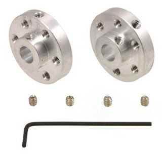
As we completed all flow chart regarding project, it is time to open SolidWorks and start modeling mechanical design.
I need to use same logic to fix main shaft and spur gear but I couldn't find internet that's why I have to do it.
Let's start!
First I am going to design pinion and spur gear. I need to drill holes to spur for fixing point to main shaft.
Now I need to draw DC Motor, DC Motor Box, Motor shaft connection equipment.
Seems good right? Yeah I think so.
I am going to use 3D Printer to produce gear set, main-housing and some main-housing's sub-parts.
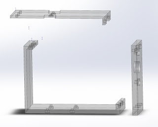
First I designed main-housing as single part and it will take 15 hours to print. If I have any form disorder after printing, I need to print again. Therefore I am going to divide main-housing into 3 parts.
With this way I will reduce wasted time if I have any printing problem.
We need to use pillow bearing to fix drive shaft to our main-housing. For this reason I am going to use two pillow bearings. One of them will be located in main-housing front side, other one will be in middle side. With this way our shaft will be fixed. By the way, I need to design extra sub-part to fix middle side pillow bearing to main housing.
I almost complete mechanical design. Welding main-shaft to ABS shaft hub was hardest part of mechanic design. Because shaft is more weak than ABS shaft hub. When I tried to weld, the shaft was shrinking. Becuase of this shrinking, ABS hub was shaking in the operation.
I should get short main shaft becuase it can effect incresing wobbling while running.
This is the first manual running test. So far so good. See you in next note.


Comments
Post a Comment